WHAT IS WAS
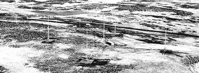
Sanak, AK Radio Range (FAA Archives / KadiAk.org)

GENESIS OF THE LOW FREQUENCY RADIO RANGE (LFR)
First implemented in 1928, LFR was a system of specialized low frequency radio stations that each projected 4 “beams” that interconnected to form a network of radio airways that pilots could follow in low visibility conditions by listening to auditory cues over their radio headsets. The beams were created by two overlaid signal patterns emitted by two pairs of antennae in an “X” configuration, one a Morse “A” (dot-dash) code, the other a “N” (dash-dot) code which synced along each leg to create a continuous tone when a pilot was “on the beam” or on course. If a pilot tracked off course, either the A or N code would be heard over the other, indicating the direction back. These aerial “highways of sound” were the first viable solution to a problem that had long dogged aviation since its first days and had thwarted its progress by the 1920’s.
As soon as the first aviators stumbled into fog, it was recognized that “blind flying” or “instrument flight,” (the ability to pilot a plane through the densest weather without any reference to the horizon or ground) would be fundamental to reliable, scheduled air travel. By the early 1920’s gyroscopic instruments, first the turn and bank indicator and later the artificial horizon, would solve the first problem: giving pilots a sense of “up” in the spectacularly disorienting conditions within the clouds (this hard lesson was and is still learned the fatal way by untrained pilots). However, this technology could not guide pilots to their destination - more was needed.

In these early years, aviators navigated solely by “pilotage:” visually following rivers, shorelines and railways (the nation’s highway system was still in its infancy) and marking progress against the towns, mountain peaks, etc. that were passed by. These waypoints may or may not have been conveniently located along their desired course and were not readily visible at night or through clouds. Starting in 1924, the hundreds of lighted towers of the US Transcontinental Airway System became the first ground-based navigation aid that defined a fixed, direct airway. Day and night, pilots could follow the series of 50’ towers spaced 10 to 15 miles apart, each with a visible concrete or metal arrow at its base and topped by a 24” wide rotating beacon that could be seen for 40 miles on a clear day. The US Air Mail Service promptly used it to demonstrate aviation’s clear potential by whisking mail coast-to-coast through the “gloom of night” in the then unprecedented timeframe of 2 days. By 1927, it expanded to an initial 4,100-mile network of "Federal Airways" encompassing Los Angeles, Dallas and Atlanta. Although it achieved around the clock air service, all traffic along it was still brought to a standstill the moment any weather obscured its lights. However, another nascent technology would soon provide the key to true “all weather” navigation.
Aviation and radio started their lives in parallel at the beginning of the 20th century. Early on it was realized that the latter technology could penetrate the night and poor weather to help pilots find their way. As early as 1888, it was realized that loop antennae are highly directional, and were most sensitive when the ends were pointed at the signal, and picked up no signal at the “null” when the antenna was face on. This principal allowed the development of a “radio compass” that could point to any radio source, whether a purpose-built beacon or a commercial radio station. In 1920 a US Navy Seaplane successfully used one to locate a ship 100 miles offshore. However, in the era of vacuum-tube radios the technology was complex, bulky, temperamental and expensive – only larger planes could carry the weight. Additionally, until World War II, most systems required that a pilot manually turn an antenna or turn the entire plane to find a signal – and even then, it couldn’t immediately tell the pilot if he was moving toward or away on that bearing line (the “180° ambiguity” problem). If there was a continual crosswind, a pilot could actually fly a curved course to the beacon per the diagram below. “Tracking” at a slight angle to compensate could help, but as winds could fluctuate along a course, it was not precise.
The ideal system would allow pilots to use cheap, light equipment to track a fixed course - just like following the airway beacons along the ground - which made it easier to fly a straight line with a crosswind, avoid hazards such as high terrain and allowed for better separation of two-way air traffic along a course.

The answer that became the Low Frequency Radio Range system was first made workable by the Ford Motor Company. A patent was filed in 1928 by Eugene S. Donovan, the lead engineer on this effort. It’s early development was rooted on a concept patented by German scientist Otto Scheller in 1907 that was further experimented with by the US Bureau of Standards and Army Signal Corps. Henry Ford personally saw the future of aviation and wanted to part of it, stating in 1924 “it is now or never to get a hold of commercial flying and make a success of it.” He placed his considerable financial resources behind his ambitions, buying out Stout Metal Airplane, the company that would later make the famous Ford Tri-motor, and building a new state-of-the-art Ford Airport at Dearborn, just outside of Detroit.
In 1926, as part of this initiative, Ford engineers looked to perfect a reliable radio beacon to help them ferry auto parts between their Chicago and Dearborn plants using Tri-Motors during the brutal Midwest winter. The first station at Ford Airport was built and licensed by October 1926 and by February 1927 the system proved to very successful. Citing the transformative impact it would have on aviation and the public welfare, and considering perhaps the probable growth in sales for its aviation division, Ford declined to collect royalties from US Government for using the invention.
Progress was very quick once the 1926 Air Commerce Act empowered the US Department of Commerce's new Bureau of Air Commerce to establish a system of radio navigation aids along the Federal Airways. They, in turn, enlisted the US Bureau of Standards to find suitable technology. Experimental work commenced at their College Park, MD station in December 1926, and test runs began between additional demonstration stations at Hadley Field NJ, and Cleveland, OH from December 1927 through February 1928. Right after that point, the Bellefonte, PA station went on-air as the first commercially available Federal range station. It was joined by the two earlier demonstration stations to establish the first “Radio Airway” between New York and Cleveland in November 1928. This grew to 9 stations by 1929. On September 24th of that year, James Doolittle, who would go on lead the famous raid on Tokyo in 1941, successfully took off, circled and landed a plane with a tarp-covered cockpit using a radio range and another specialized radio beam for landing, proving once and for all that flight solely on instruments was possible. Coast-to-coast service from New York to San Francisco was achieved in 1931. By 1935 the US Mainland was crossed by a network of 117 stations, and by the end of World War II over 400 were in place with a couple hundred more across the globe.
The LFR system was considered an "indispensable" godsend in its era – for the first time, pilots could reliably navigate long distances without seeing the ground. Its development received front page coverage in the press and popular media as a major technical achievement.

HOW THE LOW FREQUENCY radio RANGE WORKED
The crux of LFR was simple. The airways were established by the "beams" projected from hundreds of stations, typically at a significant intersection or airfield. Pilots would listen to their signals by tuning into stations with simple, relatively cheap AM radio sets in the cockpit with headphones, about the same size and cost of small tabletop radios from the era. All guidance was provided by audio tones, there were no other specialized instruments. This kept costs down and helped speed LFR’s adoption - Uncle Sam provided and maintained all of the heavy, expensive equipment on the ground. LFR was simultaneously the first nationwide radio communication network that could reach aircraft in flight. As covered in the next section, this ability was first used to broadcast regular weather reports to aviators and then to help establish the US air traffic control system.
Each station had two diagonally opposed sets of vertical antennae that transmitted a figure 8 directional pattern of radio waves at a 90° angle to each other per the diagram above creating four sectors or quadrants. Two antennae emitted a Morse code dash-dot tone, the “N” signal, into the two yellow quadrants and the other pair emitted the dot-dash tone, the “A” signal, into the two opposite blue quadrants. Note that each signal was an exact negative of each other, the noiseless gaps in one signal were synced with the dot/dash sounds in the other. When the pilot was equally placed between the towers on the line that separated the quadrants, whether it be one mile away or fifty, both signals would be of equal volume and precisely intermesh into a steady, continuous 1,020 hertz tone. These four lines were the “legs” or “beams,” the course a pilot would fly along. When “flying a beam,” if a pilot heard that simple monotone, they knew they were on-course, or “on the beam”, and that is how that term entered the American lexicon in the mid-20th century. If the pilot was closer to the A side or the N side, that tone would become dominant, and the pilot would make the necessary course corrections. These beams were roughly 3° wide and could extend from 50 to over 100 miles from the station.
If a pilot was on the edge of the beam in the “twilight” zone, about 1° wide, one signal would faintly emerge above the other – not enough to be clearly distinct, but sufficient to tell the pilot to make a slight correction. When there was two-way air traffic along a beam, standard practice was for opposing aircraft to fly the right twilight edge of this beam to ensure proper separation. Farther away from the beam, both signals (one much louder) could be easily distinguished in the “bi-signal” zone. Deeper into a quadrant only one signal would be heard, the “pure quadrant” or “clear” area – especially at the “bisector,” a line in the middle of each quadrant equidistant from the beams at either side. These variations were subtle but could provide clues to help a pilot navigate to a beam.
Every 30 seconds a two-letter Morse code station identifier (lasting 8 seconds) was repeated first on the N side and then on A side in Morse code to allow the pilot to confirm that they were listening to the right station. For example Los Angeles was “LA”, Chicago “CG”, etc. Starting in the 1940's, some station identifiers were changed to three letters (for example, “LA” became “LAX”) due to the increasing number of overall radio facilities.
Recordings of an actual range station can be found on the next page

A pilot could tell that the plane was approaching a range station when the volume in the headphones would “build” or steadily increase. When a pilot was over the range station, as the radio waves from like A or N antennae cancelled each other out above the station, both signals would suddenly die off (“fade”) in a “cone of silence” then, just as quickly, resume which became proof-positive that a pilot was directly over the station. Additionally, the A and N sides would reverse. After 1938, many stations added a “Z” marker, a second upward pointed radio beam that would activate an amber beacon light on the instrument panel and a 3,000 Hz tone in the headset to more positively confirm the crossing.
Flying between ranges, the system could not tell one the distance from any station. As such, the ranges were complimented by additional similar “Fan Markers”, which as the name implied, had a wide 3 by 12-mile elliptical or bone-shaped beam spread perpendicular to an airway to mark particular waypoints. While Z markers emitted a continuous signal, fan markers instead emitted a series of dashes depending on their direction from the reference station. The marker on the first beam clockwise from true north would sound 1 dash, the second 2 dashes and so on up to 4 dashes. When an aircraft passed over one, the same receiver would mark its dashes with the 3000hz tone or light to make a positive ID. If there were 2 fan markers on the same leg, the outermost would be preceded by two dots to differentiate it. By World War II, secondary Low Powered Fan Markers were placed on beam legs that passed over airports as part of early Instrument Approaches discussed in the next section. These 5-watt markers were located about 2 to 4 miles from runways to alert pilots of their proximity. These were keyed like fan markers, but also used the two-dot prefix. These would later evolve into the marker beacons used with Instrument Landing Systems.
Finally, another helpful aid was that, in the US, true north from the station always lied in an N quadrant, which meant that there would generally always be north and south N quadrants, and east and west A quadrants. In Canada this reference line was shifted 45° west to 315°, which in theory would allow the 4 beams to better align to the cardinal compass points but created northwest and southeast N quadrants, and northeast and southwest A quadrants.

AIRWAY COMMUNICATIONS ON “THE RANGE” & THE BIRTH OF ATC
LFR is certainly best known for radio navigation. However, the notion that a nationwide system of radio stations could double as an aviation communication network wasn’t lost upon its inventors, first to make flying safer by broadcasting the latest weather conditions to aircraft on their journeys and then later as a founding piece of the nation's air traffic control system, and is an often-overlooked story. As a 1954 Air Force flight instruction manual later summed up “radio ranges and marker beacon facilities have become the basis for airways navigation and control; without these, systematic procedures could not have been developed.”
Early experiments with push-button “radiotelegraphs” confirmed that it was simply unrealistic to expect pilots to simultaneously fly and transceive long messages in Morse code. As it wasn’t practical to saddle every aircraft with a dedicated radio operator it became clear that aviation demanded voice communications. Fortunately, the affordable and compact vacuum tube cockpit receivers specifically developed for LFR already included this new capability, which meant right from the start every pilot that used the system could also hear a voice broadcast. After their promise was shown during the First World War, the two-way “radiotelephone” also became practical for aviation by 1930. Additionally, the teletype had matured by this time into nationwide networks where volumes of information could be disseminated as quickly as one could type, from stock quotes, police bulletins to the latest news. As the Bureau of Air Commerce rolled out LFR along the Federal Airways after 1928, it repurposed the older airmail radio stations it inherited, originally intended for just station-to-station ground use, as Airway Radio Stations (after 1936, Airway Communication Stations or ACS) and used all these developments to give LFR two more critical capabilities.
The first was the regular broadcast of current and forecasted weather reports from the ACS over all LFR stations to any aircraft on their part of the network, typically every 30 to 60 minutes, 24/7. This was made possible by the National Weather Bureau which collected dispatches from its army of weather observers. Issued by teletype to all points, current weather conditions were updated hourly and comprehensive national forecasts (including type character weather maps) posted every 6 hours around the clock, a cadence that continues today. To this day, aspiring pilots must memorize the standardized abbreviations originally invented for teletype still used in aviation weather reports. The stations were grouped into three chains and timed their broadcasts to avoid overlap. The format evolved over time, but a sample report from 1936 would start “This is Airway Communications Station Burbank Broadcasting.” It would then progress through each LFR station in succession: “Burbank, Burbank: Overcast. Ceiling 1,000. Visibility 7 miles. North Pass Open. Daggett, Daggett: Clear and Unlimited” and so on, concluding with “Burbank Radio Range is Now Being Resumed.” Finally, pilots could get a “look ahead” for their journey.
Second, for the planes so equipped with radiotelephones (which was, at first, only larger commercial and military aircraft) LFR also provided the critical two-way link to ACS. In the beginning, pilots could request updates, relay messages and seek assistance in emergencies – but this ability helped spur an even greater transformation. In 1920 London’s Croydon Airport set up the first “control tower” to manage its air traffic by signals and radio. Cleveland’s airport was the first in the US to be similarly towered in 1930 and 20 other cities soon followed suit. In 1935, the Bureau of Air Commerce urged airlines to create their own control “centers” to coordinate increasing air traffic in busy regions between airports. In 1936, it took charge and merged these into its new national "Airway Traffic Control" (ATC) system using LFR as its communication backbone along the 22,000 miles of airways its beams now defined. Now all aircraft within two-way radio range of an LFR station, even those on remote stretches of the airways far from any airport tower, could be contacted and controlled, greatly improving safety and reliability.

Working around the clock and coordinating via teletype and "interphones", center controllers could ensure aircraft separation by assigning specific routes and altitudes. Flight plans were reviewed, adjusted as needed, approved and forwarded to other ACS on the filed route. Well before computers and radar, controllers chalked up flights on dispatch blackboards, and tracked their progress by moving brass “shrimp boat” markers, each clipped with a note card of flight details, on their table maps. It is interesting to note that in this era pilots did not have direct contact with ATC, which functioned more as a behind the scenes clearinghouse until the 1950’s. Further ATC instructions were relayed to ACS who, in turn, communicated them via radio through the LFR stations to aircraft en route. Pilots radioed backwards through this same chain their position reports, noted by passage over range stations or fan markers, and any requested plan deviations. If required to manage traffic “flow” ATC could request aircraft adjust speed, circle and “hold” or alter course.
1936 also brought the requirement that all aircraft flying on instruments on Federal Airways (which was nearly all scheduled air service by this point) be under ATC control through two-way radios and have proper instrumentation. After 1941 ATC began to more directly manage airport control towers and aircraft “time offs” to better regulate access to the airways. However, the commercial sale and use of receive-only LFR radios by small planes for night flight, “marginal” visual conditions and, quite possibly, illicit blind flying on the airways (in the days before radar tracking) would continue well into the postwar era.
To avoid any confusion with an airport control “Tower,” an Airway Radio Station or later ACS called up by a pilot through an LFR station was referred to as a “Radio,” e.g. “Oakland Radio”, “La Guardia Radio” etc. During World War II, the UC Army Air Force set up its own separate “Army Airways” Communications Stations (AACS), but eventually these were merged back into a single national system in 1958. As air traffic continued to rapidly grow, ACS responsibilities were further devolved: radar equipped “Approach” or terminal control centers were set up to manage arrivals and departures from the busiest airports and the “Centers” now communicated directly with the aircraft in between. In 1960 the ACS were renamed Flight Services Stations (FSS) to reflect their remaining briefing and advisory responsibilities. However, nearly a century later, when a pilot calls up these stations from the air, the convention “Radio” is still used.

THE RANGE STATIONS & TECHNOLOGY
The stations were fairly sizeable as the low frequency radio used required larger antennae to transmit efficiently. First generation Loop Stations were square shaped and were roughly 300' on each side (2-acre site area). They had 40’ to 52' wooden masts at each corner that supported elongated pairs of “A” and “N” loop antennae in an “X” configuration across the site to create the signal quadrants and beams. Second generation Adcock Stations emerged after 1933, shown above and described in more detail below, and were about 600’ to 800’ on a side (8 to 15 acre site area). These more advanced stations had four 120' to 135’ tall riveted steel antennae towers or “mast radiators” at the corners of a 425' square, spaced 600’ diagonally, that performed the same function. As described below, Adcock stations had a fifth central tower for voice communication. Fortunately, land was cheap back then; especially for the mostly rural station sites. Federal land agents would commonly appeal to the owner’s sense of patriotic duty to secure a good deal on a lease or purchase agreement.
The system used Low-Frequency radio (190 kHz to 400 kHz, and up to 536 kHz for military ranges), just below the AM Radio broadcast range. As 300 kHz and above is considered “Medium-Frequency” some sources referred to the LF Range as the “Low-Frequency / Medium-Frequency” or LF/MF Range. These frequencies have long wavelengths, roughly 0.5 to 1 mile, that tend to travel further over the curvature of the earth as “skywaves” that repeatedly “skip” off the underside of the ionosphere. The range of these skywaves greatly exceed a station’s terrain hugging “groundwave” making global shortwave radio possible. Longer ranges were possible at night when the ionosphere is most reflective. For this reason, most stations needed only 50 to 150 watts of transmitter output power (equivalent to an incandescent household lightbulb) to be heard over 100 miles away, although some stations had up to 1,500 watts of power. As discussed later on, this frequency was also susceptible to other negative effects but this low power requirement made the station apparatus relatively economical and easy to set up, and only a cheap, lightweight AM receiver was needed on each aircraft, which greatly aided its adoption.

At lower radio frequencies, loop antennae are highly directional: greatest transmission and reception strength occurs along the plane of the antenna’s loop and is weakest at the “null” 90° to its center. When seen from this point, as the current flows in a circle around the loop, the emitted radio waves from any portion of one side is equal and opposite (180° out of phase) from an equivalent portion on the other side, cancelling each other out. Conversely, any radio signal sent from this point would induce equal and opposite currents around the loop that would also cross-cancel, creating a null in reception - radio compasses aligned a loop antenna to this null to determine the direction of signal. At LFR loop stations, separate A and N loop antenna at 90° emitted two opposed signal lobes along their lengths which appeared from above as crossed figure-eight patterns forming the 4 quadrants. The beams formed where these signal lobes were in balance, as both A and N signals would interlock at equal volume along this line.
Additionally, the signals at either end of identical A or N antenna pairs were transmitted a half wavelength or 180° out of phase with each other. This meant that when both sides of these antennae were seen as exactly equidistant, as would be case if one was directly above the station or along one of the bisector lines, their inverse signals would cancel each other out – forming the “cone of silence” and the “pure quadrant” or “clear” zones. As can be seen, signal phase and cancellation effects were critical to creating the full anatomy of the signal pattern.

Loop stations were simple but required that horizontal wires be strung hundreds of feet between masts where they and their beams were exposed to the effects of wind. However, a larger problem soon emerged: the long, flat portion of the loops sent significant amounts of horizontally polarized radio energy upward, which the ionosphere would efficiently bounce back down as skywaves that could be out of phase with the stations’ own groundwave signal beyond a 30-mile radius, especially at night. Further, the ionosphere’s “D” layer, which actually absorbs radio energy at 30 to 60 miles above the earth disappears with the absence of the solar wind at night, exposing the underside of the much more reflective “E” or “Kennelly-Heaviside” layer 60 to 90 miles up, which is why distant AM stations and LFR signals could be heard much farther at night. The disappearance and reemergence of the D layer at dawn and dusk creates an even more dynamic distortion. Both phenomena, of which the science was just being understood at the time, could cause the beams to unreliably “swing” back and forth which LFR users termed “night effect.”
In 1919 British Engineer Frank Adcock determined that two electrically connected but physically separate pairs of rigid vertical antennae acted as a more effective version of a loop antenna. In 1933, US Bureau of Standards scientist Harry Diamond realized this antenna form, lacking the troublesome horizontal lines, would nearly eliminate the skywave problem by transmitting all of the radio energy outwards as vertically polarized waves. The Bureau of Air Commerce, not wanting to reference the name of a British inventor, initially called these new stations the “T-L” or "Transmission Line” type. However, common sense would prevail and “Adcock Range” became the common term. 28 stations would be so upgraded by year’s end and they would be dominant type going forward. However, loop stations would still be used for many medium and lower power sites as they were simply more economical with their smaller size and wooden masts, especially during the steel shortage of World War II.
Adcock ranges also solved another nuisance: with loop stations the range signal had to be shut down to allow the voice or weather broadcast. Pilots who had the ability to transmit sometimes had to ask the operator to suspend a report if they were in the middle of an approach or other critical phase - others not so equipped could very well be forced to restart the sequence. Nearly all Adcock stations added a dedicated fifth center antenna and a “simultaneous transmitter” that could handle the voice communication separately to allow the range signals to run uninterrupted. As a result, such Adcock ranges were also referred to as “Simultaneous” ranges. During World War II, many loop stations gained Simultaneous capability by adding a third separate broadcast antenna, or using a US Navy method of superimposing the voice signal on both loops.

The building at the center of each range station went by many names: among others, “transmitter building”, “electronics hut”, “electronic facilities building” or just “blockhouse.” This site uses this last, simple term. It was a generally utilitarian structure approximately 500 sf in area that housed the transmitters (16’ wide by 32’ long was a common size). They were built to standardized plans but construction type varied by what was common to a region, from cast-in-place concrete, masonry block, wood frame to metal construction. The Kunming station in China was even built with locally made mud brick.

Radio equipment was furnished by mainstream commercial manufacturers (Bendix, Federal Telegraph, Westinghouse, Wilcox-Gay and others) that used vacuum tube electronics that had become widely available after 12 years of industry patent disputes were finally settled in 1925. By the early 30’s it was also one of the first widespread uses of quartz crystal oscillators, the precise time regulators that established a stable carrier signal and still used in most wristwatches today. This type allowed for closer spacing of station frequencies as they were less prone to “drift” than older tube-based “tank circuits." All this gear was universally furnished in the form of tall black metal cabinets, roughly 6’ tall and replete with analogue dials and switches, lined up along the sides of the transmitter room. Adequate clearance was provided for maintenance and to dissipate the copious amount of heat its dozens of tubes generated. Each station housed two dual-redundant transmitter units that could automatically switchover if one failed and to facilitate routine maintenance.
If commercial power was ever lost (assuming that it wasn’t a more rural site that already generated its own power), an automatic standby gasoline or diesel generator provided in a separate room or a nearby detached hut would kick in, started by a battery pack that also briefly sustained uninterrupted power to the transmitters during startup. One example still in place at a former site has a nominal 12.5KVA (roughly 16 horsepower) output and used a 6-cylinder gasoline engine to drive its alternator and DC exciter.
The transmitter signal was fed to an automatic telegraph key or "link circuit relay" triggered by revolving, notched Bakelite disks (akin to a music box) that continuously keyed the dots and dashes for the signals and station identification – it effectively alternated the signal between separate A and N circuits. Given its importance, later stations also incorporated a redundant backup key.

The keyed signals were then sent to the antennae through a radio goniometer, a signal transformer consisting of two nested coils, an outer primary pair set at 90° to each other energized by the separate A and N circuits that induced an inner rotating secondary 90° pair that fed corresponding A and N antennae circuits (the polarity of one antenna in each circuit was reversed to be 180° out of phase with the other to create the cancelation effects described above). Rotating the inner coils changed the amount of energy each antenna picked up, effectively rotating the entire beam pattern without physically altering the antennae. This device was developed by Italian engineers Ettore Bellini and Alessandro Tosi in 1907 for the reverse application of finding the direction of a radio signal. The ability to orient a beam in any direction at will gave LFR crucial flexibility in defining or updating airways. Later stations consolidated the goniometer, automatic keys, and the “artificial lines” (described below), into a single range station "coupling unit.”
Beam alignment was critically dependent upon the relative signal strength of the four antennae as they formed exactly where their signals were in equal balance. Thus, the antennae needed to always maintain a specific set power ratio to each other, despite the electrical influence temperature changes, surface moisture, power fluctuations, perching birds and other transient phenomena could have on the system. In theory, the same active transmitter fed all four antennae through the key switch and goniometer in the coupling unit, electrically tying all of these components together so that they would equally respond to voltage or impedance changes anywhere in the circuit. This was similar in principle to how, in some older homes, all the lights would simultaneously dim in response to a large motor starting up. Although the overall station output may have slightly fluctuated, as long as it impacted each antenna proportionally, this crucial equilibrium was maintained.

Although the goniometer could “spin” the entire station beam pattern as whole, altering this balance was key to “bending and squeezing” the beams and quadrants to be other than just 90° apart. As described in the next section, this was also critical in defining airways. Course “shifting,” or reducing a pair of A or N quadrants relative to the other pair was done by increasing the resistance of one antennae circuit with a “course shifting pad,” a bank of variable resistors. This reduced the strength of these quadrants allowing the other pair to expand, shifting the beams. Course “bending,” where one A or N tower in a pair pushed back its counterpart, was accomplished by adjusting the “artificial lines” - a set of adjustable coils and capacitors that altered the impedance and effective electrical length of the circuit to each antenna, simultaneously increasing one while equally shortening the other. The signal from the antenna on the longer side would lag behind the other, so they no longer completely canceled each other at 180° out of phase. Instead, the waveforms of these two signals would sum together and constructively add more power at one tower and destructively cancel some of the strength at the other, shifting the beam. Through these effects, nearly any course geometry was possible.
For loop stations, the signals were sent up a center mast next to the blockhouse that fed the antennae. These were simple cable loops held taught by glass insulators suspended by conventional 40’ to 52’ wooden utility poles in the familiar “X” configuration. Although some later US Navy Simultaneous loop stations overlaid the voice transmission over these same aerials, others added a third broadcast antennae as a simple dipole with its ends stretched to a separate set of masts between the A and N loops. This cheap, straightforward design greatly sped erection time which was a definite advantage that offset its major drawbacks, especially in theatres of war. Loop stations lacked artificial lines, and instead added a “course bender” antenna to the center mast which resembled a guy wire set at a 45° between the main aerials. It introduced a third signal phased to similarly add or subtract power from the two closest loop ends, altering their courses.

Adcock antennae or “mast radiators” were certainly more expensive and complex, but were usually justified by their superior performance. They were more impressive 120’ to 135’ tall 4-sided vertical lattice trusses, about 6’ wide at the base, typically made of several prefabricated sections of riveted angle iron. They tapered to a 1’ cross section at the top fitted with a red anti-collision light that also made visual identification of the station possible on clear nights. This height was actually less than ideal as antennae should be at least 1/8 wavelength or around 300’ to 600’ for LFR, but it was a compromise made for economy and due to the proximity of many stations to airports. The self-supporting towers also lacked guy wires that could cause interference. The antennae towers stood on top of squat, truncated 8’ pyramidal bases of heavier steel members that transferred the wind forces (significant at many sites) to a reinforced concrete foundation.
Each of these masts rested on four large ceramic insulators at the corners of this base (pinned in place solely by their weight), while a fifth center unit with insulated tension rods tied it down to its foundation. This electrically isolated the mast above the earth and allowed it to “give” slightly in the wind. These insulators had rain shields that prevented water from running over their exteriors, which could ground and short circuit the antenna. This could “swing” or misalign the beam with severe consequences (at least one flight was downed by this) and was a particular problem in deserts when storms wetted the conductive alkaline dust that coated exposed surfaces. The antennae were fed by shielded coaxial transmission lines, that ran from the blockhouse either underground or via ground level supports, to minimize signal leakage and stray skywaves. In some later stations these lines were filled with dry pressurized nitrogen gas to keep water out. These were connected via a “tuning unit” or “coupler” located in a small aluminum housing in each antenna base, which better matched each mast’s impedance and natural electrical resonance with the rest of the station, optimizing its signal.
A mast radiator needs to have a good electrical ground (calibrated through the tuning unit) that permits electrons to easily oscillate back and forth between itself and the earth at the carrier wave frequency to generate the radio signal. This also allows the earth’s surface to act as a “ground plane” to effectively reflect any downcast signal back into the sky. However, many sites (especially in desert regions) had dry, rocky soil that was not electrically conductive enough to provide this. In this situation, the base of each Adcock antennae was also fitted with a “counterpoise,” a 50’ wide square wire mesh grid elevated about 8’ off the earth. The space between the grid and ground, in essence, became a large capacitor that could easily absorb and release electrons to substitute for a natural ground. At other sites, they also mitigated the impacts that vegetation growth, groundwater changes and nearby tides could otherwise have on the signal pattern.

A few more details for the technically inclined: an Adcock station’s center tower actually emitted a continuous omni-directional signal at the nominal station frequency (let say it was 200 kHz), and this carrier wave could be modulated for the voice and weather broadcasts. As it was continuous it could also be used as a homing beacon by a radio compass by those planes so equipped. The N and A towers actually broadcasted their signals at that frequency plus 1.020 kHz (so 201.02 kHz); the 1,020 hertz tone the pilot heard for the dots and dashes. When both signals were converted into sound waves by the radio’s electronics, like a piano chord, they blended and produced the audible, out of phase “beat” frequency of 1,020 Hz. Later radio receivers had a bandpass filter that allowed the pilot to switch the receiver to hear the tone only, voice only (as the human voice is lower between 300 Hz and 800 Hz) or both. Many aviation receivers from the era also had an “automatic volume control” (AVC) which made it easier to listen to conventional AM stations as they drifted in and out of range; however, handbooks earnestly warned pilots to always disable this feature when using the range so the pilot could properly hear changes in the signals.
The “cone of silence” was an unintended byproduct of LFR development. It soon proved to be a useful feature but it was not always reliable. Absence of a signal was not always proof-positive of a station crossing – signals suddenly died due to equipment issues, “fades” caused by terrain effects and other reasons. The cone was also easily missed at low altitudes, broad and diffuse at high altitudes, and could be tilted or narrowed from “bending and squeezing” the beams. Starting in 1938, many stations solved this problem by adding 75 Mhz Z-markers that filled the cone with a 3,000 hertz tone that could be heard in the headset or triggered an amber light on the instrument panel (US Army aircraft solely relied on the latter). This positive indication was generated by a smaller standalone 5-watt transmitter that also had two dual redundant sections for backup. Its antenna was located in the ample area between the loops or masts, and consisted of a cross of four horizontal half-wavelength dipole elements (about 6.5’ long) over an elevated 30’ square wire screen counterpoise / reflector that bounced the signal skyward.
Finally, as with any radio facility, lightning was a concern. Both Loop and Adcock stations had extensive grounding systems that included underground cables that followed each loop or transmission lines to each corner mast. Many later Adcock stations also had eight 100’ cables radiating underground from each tower foundation (a few of these trench patterns are still visible in aerials) which could also help ground the antenna in poorly conductive soils. Should lightning strike, “spark gaps” beside the insulators and/or in the tuning units allowed its much higher voltage to jump a short distance to a grounding contact where it was safely diverted and dissipated by this system, sparing the station’s electronics.

OPERATING & MAINTAINING “THE RANGE”
Nearly all stations ran unmanned, one of the first “lights out” facilities of the 20th century, illuminated only by the faint warm glow of vacuum tubes within the transmitters accompanied by the sounds of whirring cooling fans and the never ending clicking of the automatic key. Range station operators were actually located at the Airway Communication Stations tens or even hundreds of miles away (often at airport terminals) linked by dedicated telephone landlines. Standing at a specialized remote-control desk with built-in voice transmitters, microphones in-hand, they delivered the weather reports and communicated with the pilots. They could also monitor and control each station back through the same circuits using a rotary telephone-like device that could send 16 preset commands, ranging from turning signals off to allow a voice broadcast, to turning on the anti-collision lights on the radio towers at night.
As such, most stations needed only a daily inspection visit. A few exceptions such as Donner Pass, located on a frequently snowbound 7,135’ ridge, required a live-in caretaker. However, during World War 2, the Allies created a number of ferry routes to move aircraft all over the world, including the Northwest Staging Route through the Yukon, Alaska and Aleutian Islands to the USSR, the North Atlantic route via Quebec, Greenland to Europe, among others. Each route consisted of a chain of airfields and range stations through truly isolated and inhospitable parts of the globe. As these stations were often the only aviation radio facility within their 100’ mile service radius many doubled as the equivalent of self-sufficient airway communication stations manned 24/7 by resident staff.
Especially given the fact vacuum tubes were prone to occasional burnout, there was a rigorous schedule of inspection, cleaning and preventative maintenance. In addition to a fleet of mobile service technicians, numerous ground monitoring stations, a fleet of inspection aircraft and the end-user pilots themselves were all constantly checking for deviations. Any departure from normal would be investigated immediately and a Notice to Airmen (NOTAM) would be dispatched via teletype to all ground facilities to warn pilots. Later stations also incorporated an early form of automatic internal fault detection. The station would monitor its own radio output and if beam alignment drifted or an automatic key stuck, the station would transmit a series of three U’s (dot-dot-dash) between station identifiers telling the pilot to be especially wary using this station.
Although LFR was certainly not problem free its issues were at least predictable and, to a large extent, manageable. Overall, the system was thought to be generally reliable for its era. It was rare for LFR to be implicated in aircraft incidents but it occurred from time to time. TWA first faulted the Pittsburgh range for the nearby fatal crash of its DC-1 on Flight 1 on April 7, 1936; however, it was found be in satisfactory working order – pilot error and schedule pressure were later blamed. Nor was LFR to blame for the United Flight 6 DC-3 crash off Pt. Reyes, CA on November 29, 1938, but an unusually reflective ionosphere overwhelmed the pilot’s headphones with the signals of distant stations, resulting in a navigation error and fuel exhaustion. However, on November 4, 1940, early morning snow shorted out one of the antennae insulators of the Salt Lake City range which long had a troublesome operating history due to local atmospheric and terrain effects. This pushed its north beam 17° eastwards off course, sending United Flight 16’s DC-3 into a nearby mountain killing all 10 on board.

LFR STATION CLASSIFICATION & ECONOMICS
Stations were grouped into five classes based on type and power as shown on radio facility charts and other tables. The lower power of medium range stations produced less interference due to reflected signals from terrain - an important consideration at mountainous sites:
- RA - Adcock Range ("full" power), greater than 150 Watts - range 100 miles
- RL - Loop Range ("full" power), greater than 150 Watts - range 100 miles
- MRA - Medium power Adcock Range, 50 to 150 Watts - range 50 miles
- MRL - Medium power Loop Range, 50 to 150 Watts - range 50 miles
- ML - Low powered loop antenna, 50 watts. These had about 15 miles of range and provide localized homing to smaller fields. As these were never mapped and didn’t show in aerials, we’ve maintained a separate list of these stations.
These designations would then have the prefix “S” added to it confirm that that station was Simultaneous and “B” if it had weather broadcasts. The suffix “W” would be added if it lacked voice capability and “Z” if it had a Z marker. Thus a “SBMRAZ” station was a Simultaneous medium-powered Adcock range, equipped with a Z marker, that provided weather broadcasts. Classifications for supporting stations included:
- FM - Fan Markers, as discussed above and covered in more detail here.
- H – for “Homing” or what would be classified as Non-Directional Beacons (NDB's) today. Omnidirectional beacons intended for radio compass use located at secondary airbases / waypoints, usually for Army aircraft so equipped, greater than 50 watts.
- MH - Medium Homing, same as above but 50 watts or less.
- M - “Airway Markers” were low-powered omnidirectional beacons sometimes placed at points where pilots needed to retune from one range to the next. Their signals, usually a single Morse letter keyed every 5 seconds, were transmitted on the frequencies of both adjacent stations. They could be heard over a 5-mile radius or the full 10-mile airway width. Described in the 1943 Navy Radio Navigation for Pilots, it appears that they were more common in the early years of the system but were mostly superseded by fan markers by the 1940’s.
In terms of cost, the May 15, 1939 “Air Commerce Bulletin” gave the 1938 cost of a new simultaneous Adcock radio range station as $44,000 or $813,000 in 2020 Dollars. A group of 3 medium and low power ranges also from that year cost $87,000 or roughly $29,000 per site - $536,000 in 2020 Dollars. These figures did not include the original development costs, the cost of infrastructure (power, telephone and road access) needed to support the sites or the equipment in the Airway Communication Stations, as well as ongoing maintenance and operational costs which a 1928 report stated alone was roughly half of each station’s initial cost per annum. When multiplied across the 600+ US stations that existed over the 45-year lifespan of LFR the overall program cost would certainly be in the billions in today’s dollars.
These were all the major pieces, let's see how well it did (and sometimes didn't) work...
