ITS USE
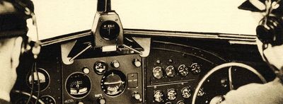
TWA DC-3 Cockpit 1930’s (World Airline Hist. Soc.)

DEFINING THE FEDERAL AIRWAY SYSTEM & PILOT CERTIFICATION
The Low Frequency Radio Range pretty much followed the original Transcontinental Airway System, as many airports and other aviation facilities were already well established along these paths. Although LFR supplanted the airway beacons, they were still a reassuring backup on clear nights – their numbers would actually increase to 2,112 beacons by 1946 before falling totally out of use by 1972. In 1938 the Civil Aeronautics Authority replaced the Bureau of Air Commerce, and in 1940 was itself split into the Civil Aeronautics Administration (CAA) responsible for managing the airways and the new ATC system, and the Civil Aeronautics Board (CAB) which provided independent economic regulation, investigation and safety rules. During this transition, the Federal Airways were reorganized into color-coded east/west “Green” and “Red” airways and north/south “Amber” and “Blue” airways. This convention has mostly fallen out of use in the US but is still used in many places internationally.
Some sources erroneously state that the first US airways were defined by homing beacons, now called non directional beacons. Although this technology preceded LFR, as described elsewhere, it still had severe limitations in the late 1920’s leading to LFR’s selection. By World War II, the automatic radio compass made this form of navigation more approachable for the larger military and civilian aircraft that could afford it and 34 homing beacons were then established, but they were still secondary to the 400+ LFR stations then extent on contemporary charts.
Under Federal law, LFR stations and their beams legally defined the nodes of the US network. Each airway was 10 miles wide and included all points 700’ or more above ground. Some stations simply had four courses spread 90° apart. However, many other stations managed to bend these legs in a “scissors” or “crow’s foot” fashion as needed to create the desired arrangement of the airways. As described in the previous section, each station’s radio goniometer could adjust the overall alignment of its beam pattern, and/or power output to one or more antenna could be increased so their quadrants would expand and literally push back on the others, “bending and squeezing” the beams in-between to the chosen angle. This effect also worked in 3D and could sometimes deform or tilt the cone of silence, an important consideration for pilots.
Pilot licensure became compulsory in 1927 but, at first, there were no other requirements for “blind flying” - any pilot that wanted to could attempt it, likely to the fatal detriment of many. By 1935, concerned with growing air traffic and close calls, the Bureau of Air Commerce temporarily banned non-commercial pilots from blind flying within 25 miles of an airway centerline until it implemented its new national Airway Traffic Control (ATC) system the following year. With this change, clear rules governed the conditions “Contact” (or “Visual”) Flight Rules were allowed, and when Instrument Flight Rules (IFR) were mandated. IFR flight now also required an “instrument rating” and all applicants that sought it would have to demonstrate to a pilot examiner their proficiency in flying a plane solely on instruments “under the hood” in a partially tarped cockpit with enough of the windscreen left open for the examiner to act as a “safety pilot.” Later on, orange plastic film would be custom fitted to the interior of the windscreen while applicants and aspiring students wore blue glasses which would effectively render their outside view black (today, eyeglass-like blinders called “foggles” are used). The applicant would also have to show their mastery of LFR by locating and establishing themselves on a beam via the complex “orientation” procedures described below, and then by executing an instrument approach. It was not an easy task: as stated in later CAA training materials “it separates the men from the boys.”

"FLYING THE BEAMS," USING THE LOW FREQUENCY RADIO RANGE
As is done today, pilots embarking on instrument flight would first develop their flight plans in consultation with published charts and procedures, consider their equipment and fuel requirements, and evaluate alternate airports. Next would be a visit or phone call to an Airways Communication Stations (ACS, now Flight Service Stations) where a briefer would pull the latest Notices to Airmen (NOTAM’S) and weather conditions from one of the constantly clacking teletypes. After careful review and analysis, the flight plan was filed, forwarded to ATC for approval and then quickly dispatched to all the airway stations en route. Once in the cockpit, checklists were ran through, engines started and the radios switched on. After an eternity by modern standards (about 10 to 30 seconds), the vacuum tubes warmed up and the first crackles were heard over the headsets. Once airborne and out of range of any control tower, the initial range station would be tuned. On well-equipped flight decks this would be done by a more precise “coffee grinder” type dial located over the pilot’s head; more modest aircraft had to make do by carefully adjusting the Bakelite knob on their sets. The station’s Morse code identifier was confirmed, and that familiar on-course tone would soon be heard as the plane established itself on the first leg of its journey.
The basic theory of flying from range to range was straightforward: as a pilot crossed the country, he (which was nearly always the case in that era) would fly the outbound leg of one station out to its maximum range of 50 to 100 miles then tune the inbound leg of the next station. In some cases, an “M” type or airway marker was placed at points between stations where a frequency change needed to be made. The pilot would often need to fly a different heading from the actual airway to compensate for crosswind but the reference to the beam would assure the plane maintained a direct course. Nearer to stations, fan markers would provide milestones to check progress against. The pilot would constantly have to adjust the headset volume as a station grew closer and louder, typically needing to lower the volume significantly just before the crossing. Suddenly, the volume would die off as the cone of silence was reached and, in many cases, a high-pitched Z marker confirmed passage. The signals would resume and fade again until the next range was tuned. Along the way, the pilot would receive regular updates of the weather ahead, and if equipped, could communicate with ATC by relaying messages through an ACS called up on a range station as “Radio.”
It all worked well under optimal conditions but, as with any first-generation technology, there were many limitations:
- One had to continuously listen to the signal over a pair of thinly padded headphones, affectionally called “skull crushers” - often for hours, in the already noisy environment of a propeller aircraft. Anecdotally, hearing impairment was a common issue as this generation of pilots neared retirement age. Early on in 1928, US Bureau of Standards scientists had proposed a simple visual indicator using a set of two side-by-side vibrating reeds. The strength of the A and N signals were shown by the amplitude of the vibration of each reed - basically turn toward the lesser side until both sides were equal. Most pilots felt it was far better and less annoying than using headphones; unfortunately, there were calibration challenges and it would still indicate “on course” if the signal suddenly stopped. The "aural" system further eliminated the expense of any such cockpit instrumentation and allowed confirmation of station ID’s merely by listening. As such, the Army Signal Corps pushed to establish it as the standard everyone would be stuck with for the next 30 years.

- The low radio frequency used was incredibly susceptible to lightning, atmospheric electricity and other similar sources of interference including the static charge that could accumulate on the fuselage by rain and snow brushing by in a storm. Severe thunderstorms could render it useless. At the precise time a pilot needed the system to work at its absolute best, it could instead be a frustrating exercise discerning faint, warbly signals above the static in a loud cockpit.
- Loop stations especially were prone to “night effect” which led to “swinging” beams. The ionosphere helpfully extended the system’s range; however, the skywaves it reflected sometimes were out of phase with a station’s groundwave, especially beyond a 30-mile radius and when this layer was in flux and dawn or dusk. This unbalanced the signal pattern causing the beams to slowly drift back and forth. The erratic nature of precipitation falling on the exposed lines of loop ranges or early Adcock towers that lack unshielded base insulators could also cause a similar, more rapid effect. At other times, the ionosphere overperformed its otherwise useful role and the skywaves from a station hundreds of miles distant could overwhelm a closer station on the same frequency. Scientists of the era were also beginning to understand that solar activity could also wreak havoc with the ionosphere, amplifying these impacts.
- The perfectly straight beams shown on charts often were not in real life. Low frequency groundwaves followed the earth’s curvature over local terrain and the horizon which, along with the skywaves, eliminated the need for aircraft to have a direct line of site with stations. However, these waves were also prone to bouncing off of mountains and other topography which could cause an A signal to “skip” into the N quadrant and vice versa, and could form false parallel “multiple courses” miles to either side of the real beam. Reflections in mountainous terrain could “dogleg” the beam by as much as 45° for short distances. Masses of steel framed buildings in cities or terrain with high iron content could “bend” the beam. Diffraction (bending) of the beam could happen due to the differing conductivity of various surfaces (e.g. water and land at shorelines, areas of differing snow or vegetation cover, etc.). Beams over coastal marshes often rhythmically shifted in concert with the tides as the groundwater content and soil conductivity below changed. That said, the peculiarities of specific stations were often well known to pilots along its airway, allowing for a level of predictive management.
- The plane’s antenna angle to the station could cause subtle impacts to the relative strength of the A and N signals and thus the exact location of where the on-course signal was received.

- Only four courses were available, and all four courses sounded exactly the same in the headphones. Most often, the legs were coordinated with the legs from other stations to create a logical airway network. But for some stations, a leg or two could point to a truly useless direction such as into a mountain range or out to sea.
- Unless you were over the actual station itself or a fan marker, there was no direct way to determine exact distances to and from a station or along a course.
- If one was lost, it was a real process to get back on the beam. With modern systems, a pilot can get their exact distance and bearing almost immediately. With LFR a pilot would only instantly know if they were in an A quadrant or an N quadrant; two opposing sectors about 90° wide and hundreds of square miles in area – not very specific. Listening to another station could help narrow it down, but there was no direct way to triangulate between them. In theory, a radio compass could help by at least providing a bearing to station. However, not all planes in this era were so well equipped and, as described earlier, these still had severe limitations. Even with this aid, the pilot still did not know the distance and time was needed to positively ID the beam and reestablish a course. Two of the most common “orientation” methods, the “ninety degrees” and the “fadeout” are shown below and required a complicated and time-consuming series of turns to determine how the signal changed in response to ascertain guidance back the beam. Pilots first were advised to calculate “average bisectors” by summing all four course bearings, dividing by 4, then adding or subtracting 90° for each quadrant. Following one of these bearings (or its reciprocal if the signal faded) would ultimately intercept a beam at roughly 45°. When a pilot finally crossed a beam a series of alternating right and left turns, each of a smaller degree, were made to “bracket” it and get back on course. If needed, the pilot would execute a “procedure turn” to reverse direction on a beam. For those pilots who were so lost in the middle of an emergency, it certainly couldn’t have been a fun experience.

- Finally, the 3° accuracy, especially when compared to modern systems, wasn’t great. If one was a hundred miles out, the beam was five miles wide. Even at 20 miles out the beam was a full mile wide, before even considering the spurious effects discussed above. This practice was generally insufficient to provide a precise lineup with a runway the way modern systems can, but it would guide a pilot directly to the airport at times of low visibility (more or less a modern day VOR or “circling” approach). The more precise Instrument Landing System (ILS), with its horizontal localizer and vertical glide slope, which could direct a pilot to the runway threshold, was just being perfected and started to see deployment just before the war. However, it's widespread adoption wouldn't occur until well into the post-war period.
Despite all these faults, the system was simple, cheap and it worked. For the first time, aircraft could reliably navigate without having any contact with the ground using only a headset. Not too dissimilar from modern standards, instrument approaches and holds were developed that allowed pilots to land at airports with low cloud ceilings and to be delayed, if needed, by air traffic control. In short, this system ensured that weather simply wasn’t a factor and regularly scheduled airline service could be established regardless the conditions. This is one of the main technologies that allowed the arrival of that Golden Age of Travel. But as always, technology was ever evolving...

The Sounds of the Low Frequency RADIO Range
What follows below are actual sounds of what appears to match the Syracuse Range (Morse code identifier “SR” or “dot-dot-dot, dot-dash-dot”) in the 1950’s, in the waning days of LFR. These recordings were specifically made for pilot training by wiring a hi-fi recorder directly into the headset feed. They were generously provided by author Barry Schiff who owned the company that developed these educational materials, who is gratefully credited for these and other contributions under Resources.
- The first recording is of plane crossing the beam perpendicularly from the N Quadrant to the A Quadrant. First only the N signal is heard, then the A tone rises until both signals merge into a steady on-the-beam monotone, then the N tone fades leaving only the A signal. Every 30 seconds the station identifier is heard.
- The second recording is of a plane on-course crossing through the cone of silence above the station. The plane first passes through a false cone of silence (typically caused by ground interference) before it passes through the real cone of silence. As the signal fades, the higher pitched “Z” marker builds and then fades, as the range signal resumes.
Again, pilots would have to listen to these signals for hours on end on a noisy flight deck, often through static and other interference.
For the audible tone engineers determined that 1,000 Hz was the ideal frequency as it fell right in the middle of the human auditory response spectrum and was readily distinguishable above cockpit noise. 1,020 Hz was selected for LFR as it was a 17x whole number multiple of the 60 Hz frequency of the US power grid which simplified oscillator design. Another source described how early testers deemed this note “pleasing”– this point may have been argued by veteran users of the system. What is also interesting to note is that the mechanical key switch technology wasn’t perfect: if one listens carefully to the on-course tone they can hear faint audible clicks as the tone switched between the A and N signals (3 clicks, pause, 1 click, pause, repeat). From the slight warbles that can heard in the tone, it’s also clear that audio oscillator stability has certainly come a long way since these recordings were made.

LFR Instrument Approaches & HOLDS
Of course, the ultimate point of LFR was to ensure that aircraft would find and safely land at their destination. Instrument “let down” or approach procedures were developed so arriving aircraft could safely emerge from the weather oriented toward the landing field, and equally importantly, knew how to successfully divert if they were still unable to see the runway. Starting in the 1930’s, pilots such as Elrey Borge Jeppesen began to document these procedures on “approach plates,” small diagrams that quickly briefed a pilot on all of the critical aspects in a portable, paperback-book sized format that could be easily carried in any cockpit. These quickly caught on, which lead him to found Jeppesen, which is still a major supplier of these charts and other aviation information today.
Today, LFR instrument landings would be considered “non precision” approaches analogous to VOR procedures where the arriving aircraft are directed toward the airport, but did not receive precise guidance up to the runway threshold as is possible with modern ILS or certain GPS procedures. As stations were often located 3 to 5 miles away from the runway, LFR’s 3° accuracy could translate to 1,000’ to 1,500’ off centerline. The procedures for non-directional “homing” beacons were nearly identical, but as they lacked any beams it was completely up to the pilot's skill with a radio compass to keep on the designated course - not an easy task with a gusty crosswind (fortunately, these approaches are now near extinct). LFR approaches took on the same standardized format:
- The aircraft first proceeded to an initial fix directly over the LFR station itself. If the airport was towered, the aircraft would begin to request its approach and landing clearances. Passage over the initial fix would be positively identified by either the cone of silence or Z marker. It would then turn to travel outbound on a specified beam that headed away from the airport. If it hadn’t already, the aircraft would begin to descend to the specified altitude for the next step below.
- After a specified interval of time (3 to 5 minutes) or distance (typically 10 miles) the aircraft would execute a “procedure turn" at a given altitude. This would normally mean turning 45° to one side of the beam, following this heading for 40 to 60 seconds, and then making a 180° turn within 60 seconds at a “standard” rate shown by the turn and bank indicator. This would allow the aircraft to re-intercept the beam at a moderate 45° angle and reestablish its course inbound in the opposite direction on a “reciprocal” heading, and then start or continue its descent.
- The aircraft would then cross back over the station, and maintain its descent until it reached a specified “published” minimum descent altitude (MDA) shown on a table on the approach plate, dictated by the aircraft class and speed. Around 500’ above ground was common. Ideally, at or before that point, the aircraft would be able to visually see or “contact” the field and land normally. Sometimes the beam was aligned along the runway and the aircraft could just head straight in, in other cases it merely pointed at the airport and the pilot would need to make a “circling” approach to line up to a runway and land.
- To ensure an adequate margin of safety (e.g. clearance from obstacles and terrain) the aircraft could not legally descend below the MDA unless it saw the actual runway in time to continue a safe approach. If it was unable to do so within a prescribed time or distance limit, the pilot would be required to execute a “missed” approach and immediately ascend to a higher altitude while turning back to re-intersect the initial fix. The aircraft could then try again or divert elsewhere.
Interestingly enough, compared to modern approaches where altitude limits are prescribed for nearly every step starting with the initial fix, generally only altitudes for the procedure turn and final passage over the station were given. Instrument holds were entered and exited along a beam line and were maintained by repeated back and forth procedure turns 1 to 4 minutes apart along the same beam anchored by the repeated passage over a station, fan marker or an intersection with another LFR station beam. Multiple aircraft could be so “stacked” at 1,000’ intervals to manage traffic flow to airports.

During World War II, the plate format became more standardized and after 1947 the CAA began to take over the role of designing and publishing these approaches. That said, many pilots to this day still prefer the format "Jepps” offers versus the FAA issued charts. As time went on, Standard Instrument Departure (SID) and Standard Terminal Arrival (STAR) plates would be added to establish procedures for these phases of a flight. Although VOR, ILS and later GPS replaced LFR, the concept of the initial fix, timed procedure turns, and approach minima are still very much part of modern approaches. One major change is current systems allow greater latitude in locating initial fixes at more convenient points for arrivals other than just right over a station. For those instrument rated pilots out there who are curious, three LFR approach plates are above - the "real" world versions of the simplified approach diagrams shown earier. Additionally, under Resources, one can find an early 1960's ADF/LFR briefing card and 1940's route planning charts.
Next: Its Fate